This page also features my other hobby, amateur radio. I transmit and receive radio signals to and from orbiting satellites and fellow enthusiasts from around the world using homebrewed radio equipment. I have a license to transmit signals using the callsign DU1AU. My interests include satellite communications, Morse code, and building home-brewed equipment such as antennas and automated motorized satellite tracking systems.
- HF Antenna: Center-fed fan wire dipole antenna (resonant to 40 m, 20 m, and 15 m bands)
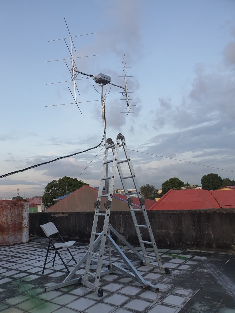
- Satellite Antenna: 4-element cross-Yagi VHF and 8-element cross-Yagi UHF antenna on an automated azimuth-elevation tracker
- VHF/UHF Antenna: Dual-band mobile antenna 1/4 wave VHF and 6/8 wave UHF Diamond SG7000, homebrewed VHF-UHF dual band dipole antenna
- Radio Transceiver: Kenwood TMV71A (full duplex VHF/UHF), Yaesu FT-2900R (VHF), Icom 718 (CW and SSB in HF), Yaesu FT60 (VHF/UHF), and Yaesu VX-6R (VHF/UHF)
- Accessories: Home-brewed straight key, home-brewed electronic iambic keyer with Uni-Ham paddles, home-brewed desktop microphone using a Sony PX470 voice recorder, home-brewed TNC for APRS operation, Tokyo Hy-Power VHF/UHF amplifier with RX preamp, Air-Spy mini SDR with Air-Spy HF upverter and NooElec LNA
- Calling frequencies: 7.095 MHz (LSB), 7.102 MHz (CW), 21.074 MHz (FT8), and 145 MHz (FM)
- Grid: PK04lk

The country where I live in, the Philippines, is a beautiful island nation with pristine beaches and turquoise waters. If we have made contact, I would like to receive a paper QSL card, and will send you one as well. I use LOTW for electronic QSL. For my mailing address, please head to my QRZ page.
DIWATA 2 Satellite Test
In March 2019, I’ve worked with the STAMINA4SPACE to test the DIWATA2’s Amateur Radio Unit (ARU). The task involves testing the receiving and transmitting capabilities of the satellite’s on-board amateur radio equipment.
DIY 40 m, 20 m, 15 m HF Dipole
I have built a multi-band DIY fan-dipole antenna for 40-meter, 20-meter, and 15-meter HF bands. A fan dipole consists of several dipoles fed at a common feed point, through an optional 1:1 balun. I have tested this antenna and I have confirmed QSOs from Philippines to Brazil (other side of the world from the Philippines, via FT8 on 15 meters) and Philippines to Sydney, Australia (SSB voice on 15 meters).
A fan dipole may be designed to operate on a number of bands simply by adding new elements to an already existing dipole, but adding new elements may change the tuning of the already tuned dipoles, making it difficult to build one that is designed to operate on too many bands. In this particular antenna build, I combined three dipoles—for 40 meters, 20 meters, and 15 meters—to form a multi-band fan dipole on a single feedline.
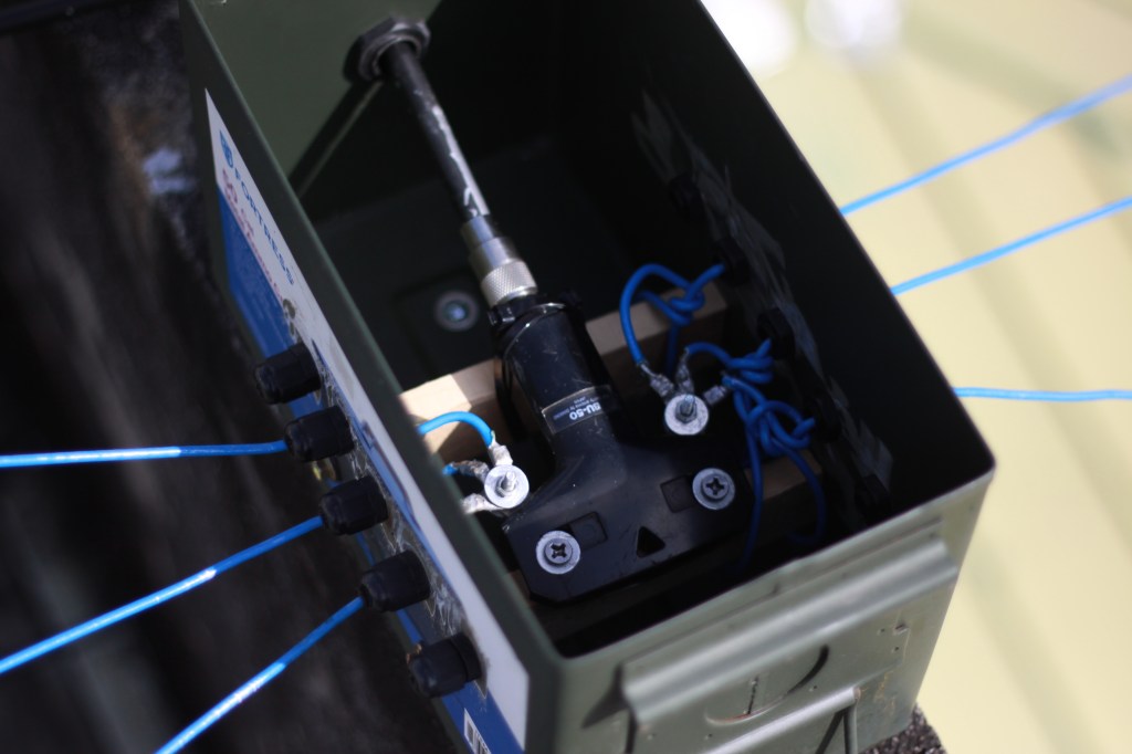
The driven elements are 12-gauge insulated wires, center-fed (split in the middle). I used a 7 meter RG8 coaxial cable feedline with 1:1 BU-50 balun. The feed point is housed in a weatherproof metal enclosure that has been placed on an elevated concrete ledge. I used non-metallic material to raise and anchor the ends of the wires, such as nylon rope.
The 40 meter band has 10 meters of wire on each sides (total of 20 meters both sides), the 20 meter band has 5 meters of wire on each side (total of 10 meters), while the 15 meter band has 3.38 meters of wire on each side (total of 6.77 meters). Adjust the lengths of the elements for lowest SWR on the desired operating frequency. Since there is likely interaction between the elements, always check the tuning of all the other bands when tuning the antenna for a specific band.
DIY Dual-Band VHF-UHF Dipole
I have built a DIY dipole antenna for VHF (2 meter) and UHF (70 cm ) bands. I used 1/4 in diameter copper tube elements. The VHF driven element is center-fed while the UHF element is coupled (placed in close proximity but not connected to the coaxial cable) with the VHF driven element. A 5 meter RG8 coaxial cable feedline is used, with no balun. The feed point is housed in a weatherproof plastic enclosure, with one side of the VHF dipole connects to the coaxial cable’s center conductor and the other side connected to the outer conductor.
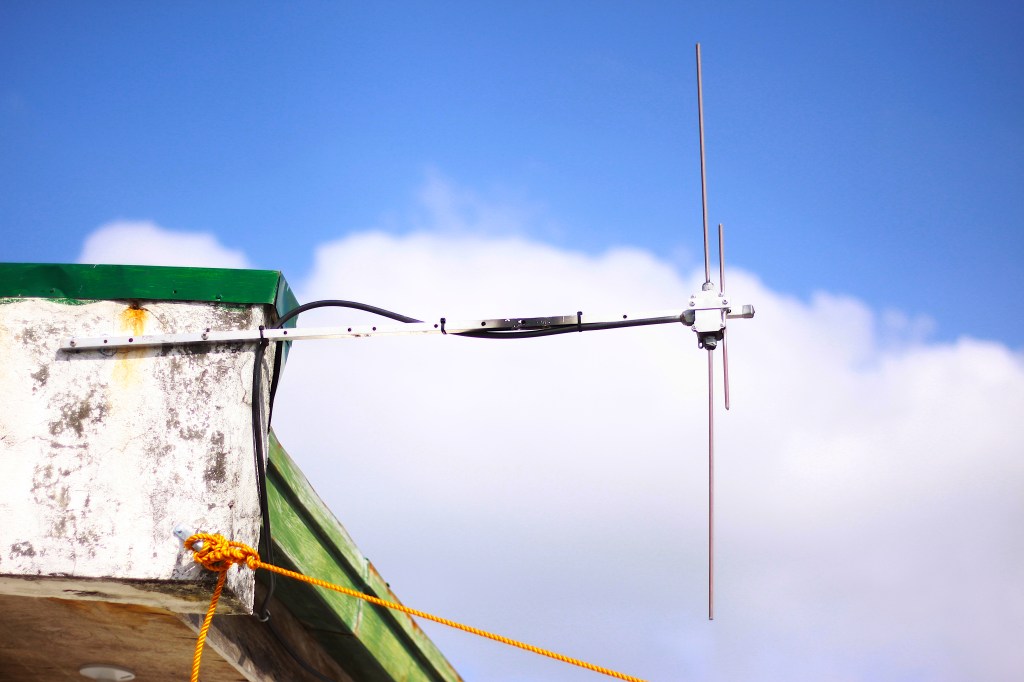
In this particular antenna, the VHF element has a total length of 984 mm (split in the center, to form two 1/4 wavelength element with 492 mm on each side) and the UHF element is 325 mm (1/2 wavelength element, not split in the middle). Adjust the lengths of the VHF and UHF elements for lowest SWR on the desired operating frequency.
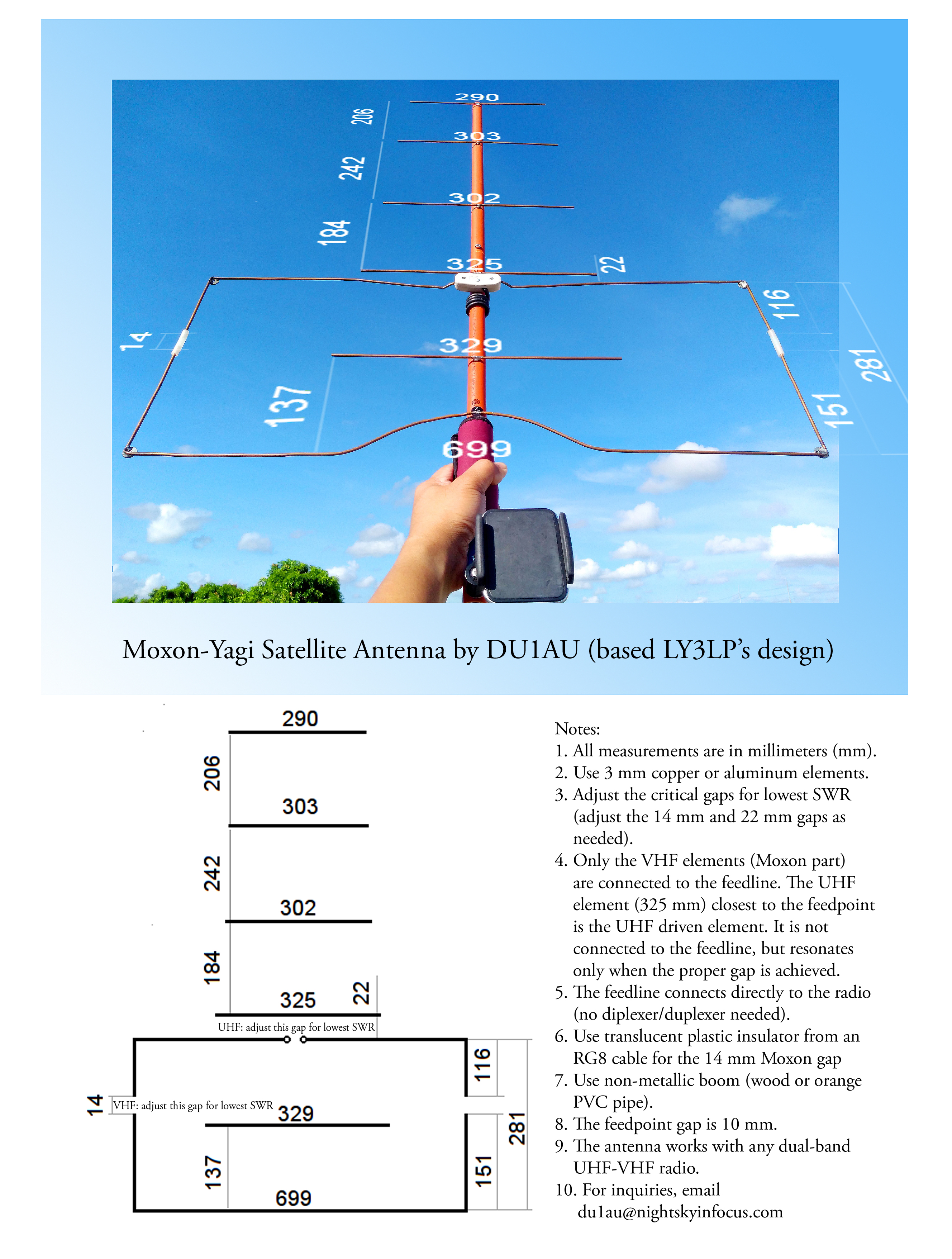
DIY Satellite Antenna DU1AU
A satellite antenna can be made from 3 mm copper or aluminum elements, PVC boom, and some parts you may already have at home. This antenna has been tested to work with the Philippine Oscar (PO)-101 satellite Diwata 2.
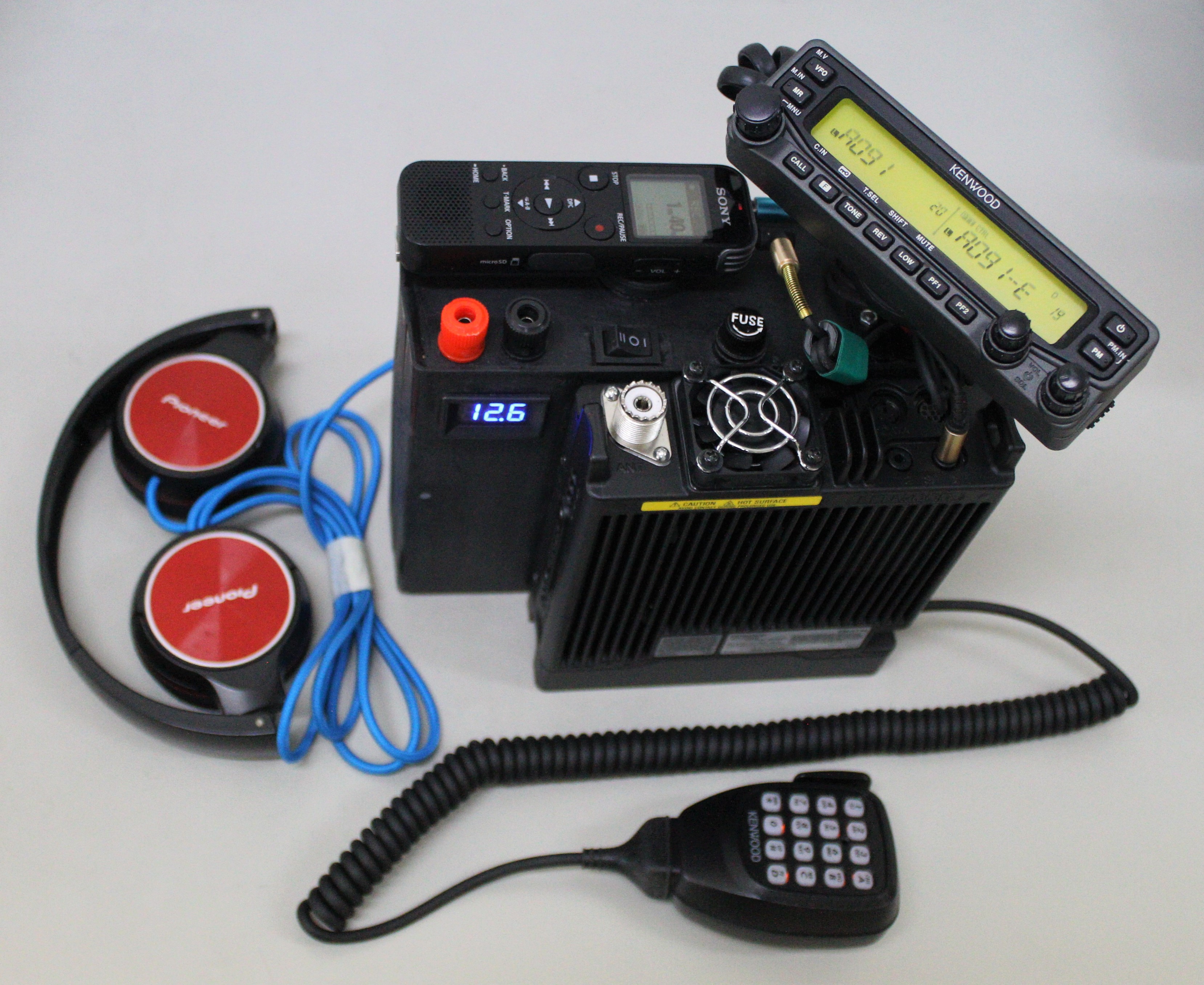
DIY Portable Satellite Radio Setup
This battery-operated radio setup can be easily carried to any remote location. Connect a satellite antenna, turn the radio on, select the pre-programmed uplink and downlink frequencies, and you are ready to make contact!
DIY SATNOGS Satellite Tracker
I’ve recently finished building a satellite traker based on SATNOGS satellite tracker. The automated tracker uses an Arduino to control a pair of stepper motors that move two cross-yagi antennas (VHF and UHF).
The Arduino receives satellite’s azimuth and elevation info using the tracking software Gpredict. Hamlib is then used to establish a link between the computer and Arduino through USB connection via EasyComm III protocol. The tracker uses two A4988 stepper motor driver, and two geared stepper motors. A weatherproof metal box is used as a case, and rubber seals prevent water from entering.
DIY SARCNET Satellite Tracker
I have built a DIY satellite tracker based on the SARCNET project. It is a simple Arduino-based motorized azimuth and elevation rotator that uses DC motors to move the antenna, and gets position feedback using an accelerometer and compass.
The tracker receives satellite’s azimuth and elevation info using the tracking software Gpredict. Hamlib is then used to establish a link between the computer and Arduino through USB connection via EasyComm II protocol.
DIY Antenna Rotator | DU1AU
I’ve built a DIY motorized antenna rotator using a geared DC motor, a pair of metal gears taken from a laminating machine, bearings, and a power window switch. The large gear is free to rotate and is attached to the mast with metal bearings. The antenna attaches to the large gear using a clamp. The small gear is attached directly to the geared DC motor. A metal bar attached to the mast is used to fix the drive motor in place, so that the gears mesh perfectly. The motor is powered by a 4.5V to 15V variable power supply to allow adjustment of the slew speed of the rotator. A 5-pin power window switch is used to control the clockwise and counterclockwise movement of the rotator. Paint is used to weatherproof the whole rotator assembly.

The DIY rotator is low cost and can be made with simple tools and materials. It is relatively easy to scale up using larger motors and better gear combination. I have tested the rotator to carry a 3-element by 4-element VHF-UHF Yagi antenna.
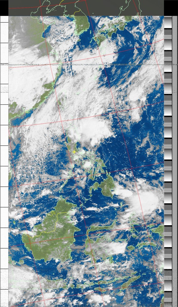
Receiving NOAA Satellite Image
NOAA satellites transmit weather images in APT format at 137 MHz which may be received using just a VHF antenna, a software-defined radio (SDR), and a decoder such as Wxtoimg running on a laptop.
DIY Bluetooth TNC for APRS
I have built a DIY Bluetooth APRS module for my Yaesu FT-2900R. The device is called a terminal node controller (TNC), for decoding and encoding Automatic Packet Reporting System (APRS) audio. This DIY TNC uses a smart phone and an Android app APRSdroid. The Bluetooth module uses the RX and TX pins of an Arduino Uno R3 to wirelessly exchange text data with a smart phone.
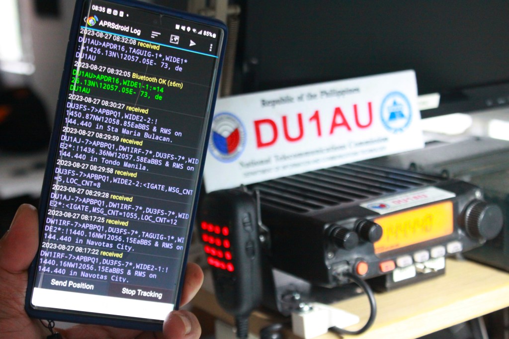
DIY Bluetooth TNC connects an FT2900R to a smart phone running APRSdroid
The Arduino connects to the input and output pins of the radio: PTT signal, audio in (mic), audio out (speaker), GND (negative), and VCC (positive). Arduino’s A0 pin reads incoming signal from the radio’s audio out (speaker), PTT line connects to a transistor which then triggers the PTT whenever Pin 3 outputs 5V during transmission. Pins 4, 5, 6, and 7 are connected to a resistor array to compose the APRS audio, which then sends signal to the radio’s line in (microphone). GND (negative) and VCC (positive) connects to the radio’s internal power supply. To view the code and the schematic diagram, head to Home-brewed TNC by VK3DAN (Daniel Phillips).
In this particular modification, I tapped directly onto the FT-2900R’s microphone and speaker port, and also the internal voltage regulator. I then housed the module in a plastic project box (do not use metal box), with a toggle switch to easily select between APRS audio from the TNC and voice audio from the hand microphone.
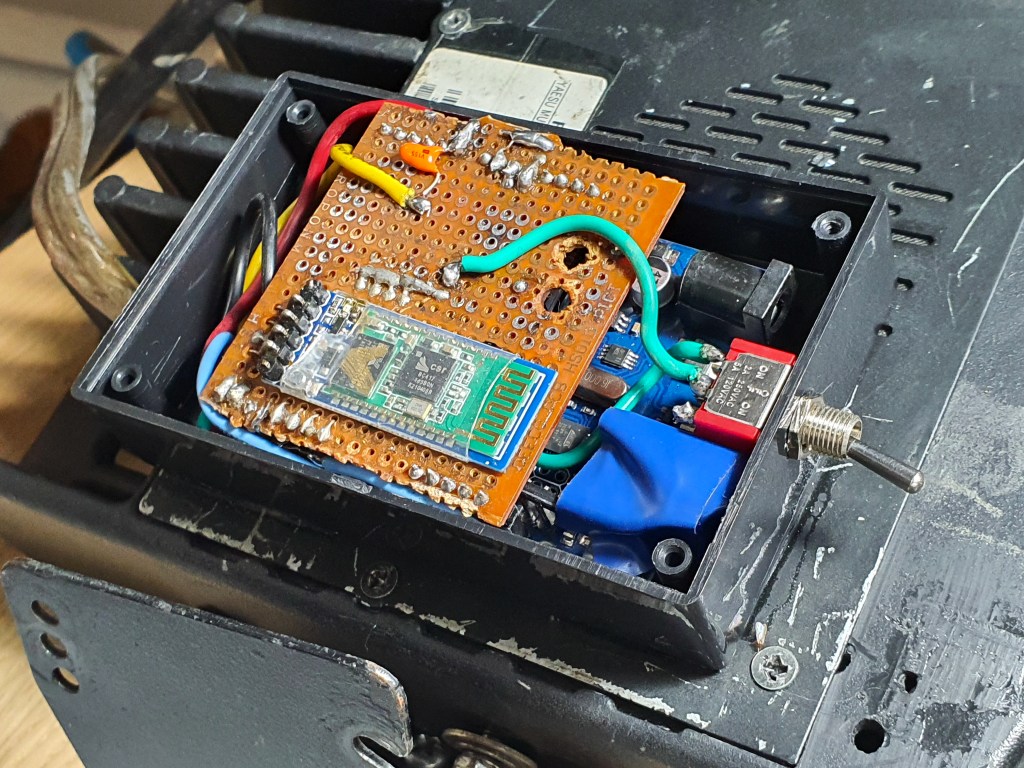
Bluetooth TNC with Arduino Uno R3 installed on a Yaesu FT2900R
An added benefit of APRS-Bluetooth connectivity is that you can be away from the radio and still send and receive APRS data in your smart phone, if within range of the Bluetooth connection. It is also very convenient to send APRS replies, since typing is done via the smart phone instead of the radio’s keypad. APRS enables radio users to transmit not only text information but also location beacons, and communicate with APRS servers and I-gates for sending data packets to the Internet. With a TNC, any radio such as this FT2900R, may be used with APRS, a feature usually found in more advanced radio units.
PSAT2 Satellite SSTV Images
PSAT2 transmits SSTV images at 435.360 MHz (UHF) which may be received using just a DIY Moxon-Yagi satellite antenna, a UHF radio, and a decoder such as Robot 36 running on a smartphone (Android). Here is an image decoded in May 2020, as PSAT2 passes over the Philippines.

SSTV transmission by PSAT2 is active only at daytime. Doppler-effect compensation is necessary to properly receive the transmission. Tune the radio at 435.370 to 435.350 MHz from start to end of the pass. You may decode up to two SSTV images per pass. To watch a a demo video click here.
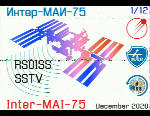
SSTV from the International Space Station (ISS)
The International Space Station (ISS) recently conducted a week-long radio transmissions test by sending encoded signals in Slow Scan Television (SSTV) image transmission format to be decoded by anyone with the proper amateur radio equipment tuned at 145.8 MHz and an SSTV decoder app such as Robot 36.

SSTV images are sent and decoded line by line, much like how scanners and printers work.
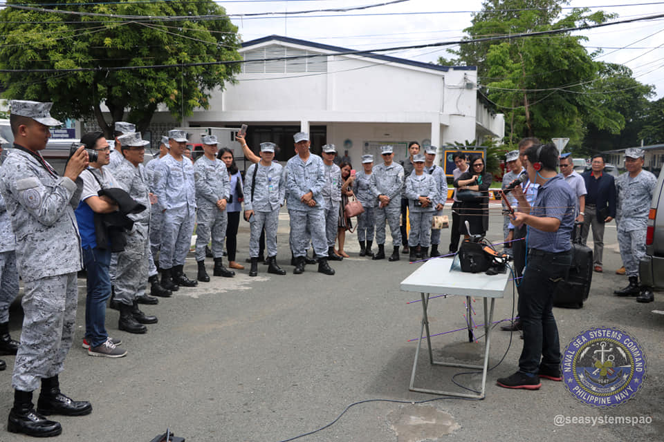
Satellite Demo with Phil Navy
I was invited to conduct a live satellite demo at the Pascual Ledesma Naval Station in Cavite, Philippines. We’ve accessed DIWATA2 (PO-101) and had successful contact with JA6PL (Japan), DV2JHA (Pangasinan), and DU1ELT (Cotabato).
DIY Straight Key and Dual-Paddle with Iambic Keyer
I have built a Morse code straight key and iambic keyer for Morse code communications. The straight key was made from brass bars, some bearings, and screw. It was then mounted on the same aluminum plate with my home-brewed electronic keyer with paddles and desk microphone.
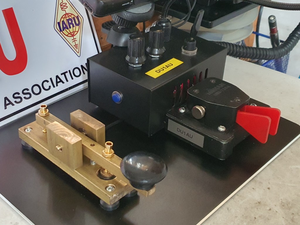
The keyer uses an Arduino Uno and a few components such as a potentiometer for adjusting the words per minute (WPM), a small speaker, some resistors, and LED indicators.
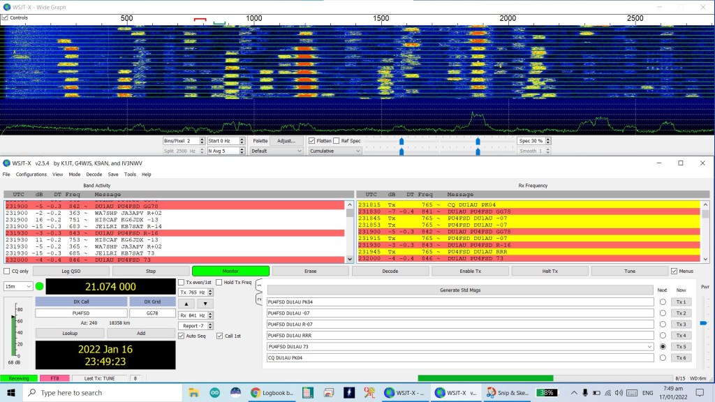
FT8 and other digital modes with ICOM 718
I have built a DIY interface for my ICOM 718 HF radio to send and receive audio signals to a laptop computer and control the PTT keying, for use with various digital modes such as FT8. I used a USB sound card for the audio interface, and a USB-to-serial port adapter for PPT keying.
The audio output of ICOM 718 (from speaker out or Pin 12 in the accessories port) connects to the microphone in of the sound card (pink port, microphone port). The audio output of the sound card (green port, headphones port) connects to Pin 11 of the ICOM 718’s accessories port. The USB-to-serial port is then configured in the settings tab of the software WSJT-X to send pulses to the the serial port’s RTS pin, which then controls a BC547 transistor to key the PTT (Pin 3 in ICOM 718’s accessories port) when transmitting a signal.
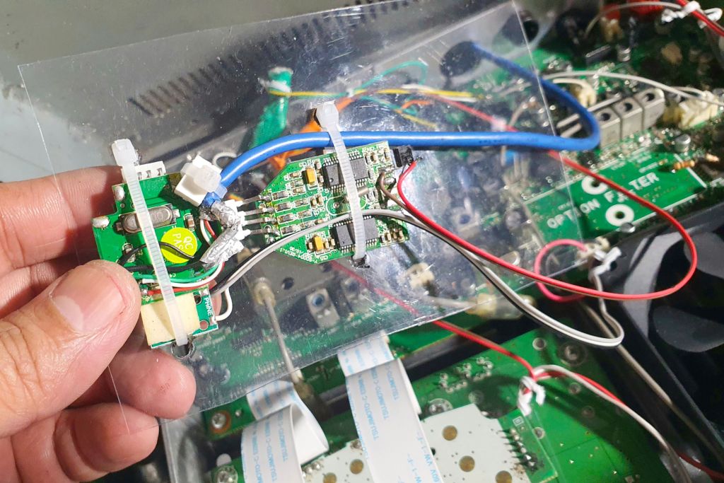
The circuit board of the USB sound card and the USB-to-serial adapter are then removed from their housing and soldered directly on to a USB hub. This configuration allows both modules to work with just one USB port of the laptop. I then put everything inside the metal casing of the radio, in a section protected from radio interference. To operate in digital modes, I only need to connect one USB cable from the radio.
During my initial tests, I was able to contact a station in Brazil (South America), from the Philippines, at 21.074 MHz (15 meters), using a 40-meter band center-fed dipole wire antenna resonant to the 15-meter band.
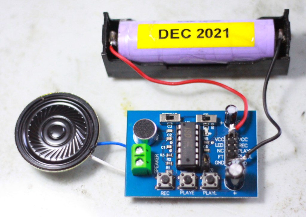
Automated Station ID with ISD1820
The ISD1820 is a sound recorder and playback module capable of storing 20-second audio recordings. It features the ability to initiate playback with a button press or a pulse, which is very useful in automated transmissions. The playback signal can be generated manually by tapping the playback button onto a radio’s PTT button, or by using a dedicated controller (such as a timer or an Arduino) for sending transmissions at regular intervals. To send the module’s audio signal to a radio transmitter such as a VHF radio on FM mode or an HF radio on SSB, connect the speaker out to the microphone line input of the radio. This module can be used to send repeated transmissions such as station IDs or for calling a CQ.
Receiving a Signal from a Wireless Microphone using a VX-6R Two-Way Radio
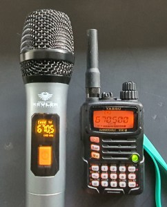
I noticed that this particular model of a wireless microphone (Kevler) displays the frequency at which it operates. It transmits signals on to a receiver dongle, which then connects to an amplifier as part of a wireless microphone setup. The microphone has a button to toggle between 30 pre-programmed frequencies from 670.6 MHz to 699.5 MHz. Realizing that this frequency range is within the receive capability of my Yaesu VX-6R two-way radio, I borrowed the microphone and tested if I could receive its signal. I typed the frequency into the two-way radio and immediately received the microphone’s signal. I found out that the signal is transmitted in FM mode. To watch a video on how I received the signal, click here.
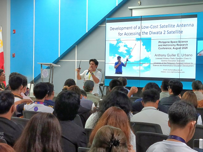
Satellite Communications With the 900th Air Force Weather Group
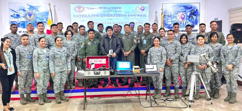
I have conducted a workshop on satellite communications on 30 April 2024 attended by thirty-five personnel from the 900th Air Force Weather Group at Villamor Air Base in Pasay City. Practical applications of satellite communications were discussed such as using satellites for emergency communications and downloading live images from weather satellites. Towards the end of the session, participants were introduced to the radio equipment, antenna, and automated tracking systems used in amateur radio satellite communications.
Night Sky in Focus
© Anthony Urbano | Bacoor, Philippines
Contact: du1au@nightskyinfocus.com
