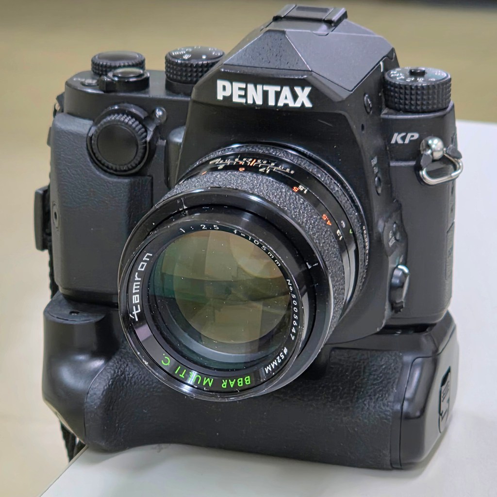
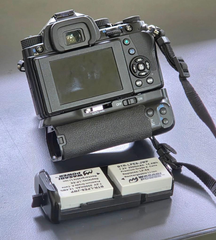
I have fitted my Pentax KP with a Neewer BG-E8 battery grip (intended for Canon cameras). While I also have the dedicated Pentax D-BG7 grip, I have made this modification to explore alternative battery options for the Pentax KP. In this modification, some filing is needed to flatten out the curved surfaces to flush the camera nicely to the grip. A new hole was then drilled in the grip since the tripod shoe locking screw was not aligned. A dummy battery was then used to connect the power to the camera. The grip’s buttons are non-functional since I have yet to figure out and map the proper connections!
I have tested my Pentax KP to work with various power supplies ranging from 7.2V to 8.4V. For instance, it was tested to work with 6 NiMH AA batteries in series at 1.2V each, it works with a Fujifilm 7.2V NPW126S batteries, it works with Canon CA PS700 7.4V power adapter, and even works with two 3.6V to 4.2V 18650 cells in series.
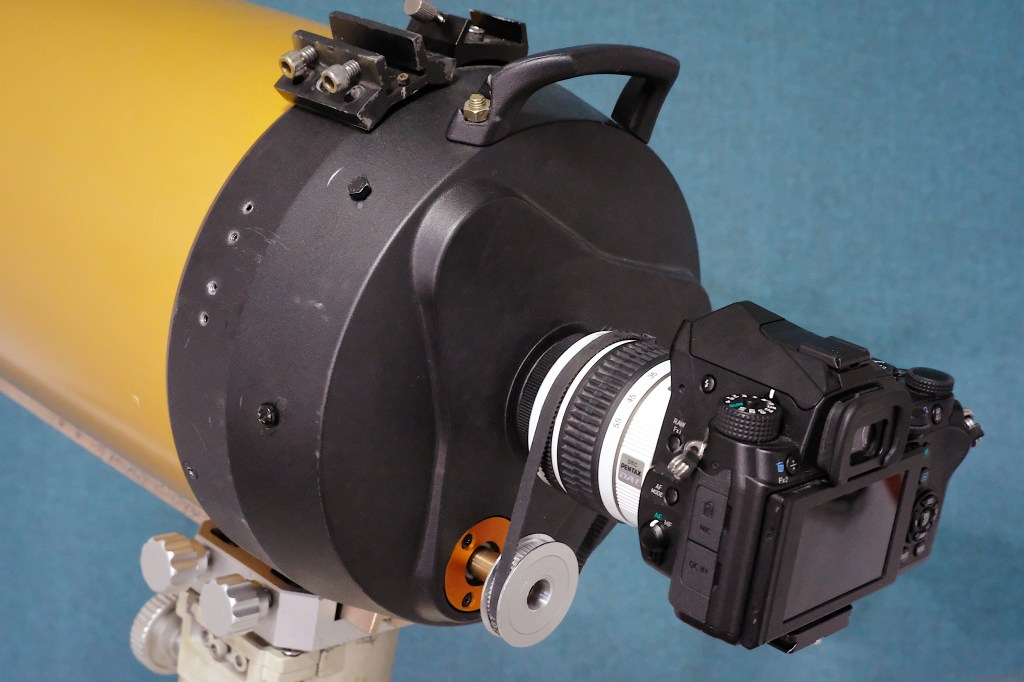
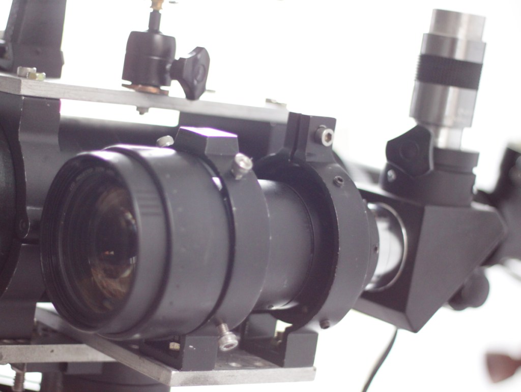
I wanted to test if it is possible to tap onto a DSLR lens’ autofocus system and use it to move the focusing knob of a telescope. I happen to have an old Pentax kit lens that works with the Pentax Screw Drive focusing system. It uses a motor in the DSLR body which is connected to the lens through some mechanical linkage. I have removed the lens elements of the kit lens and used improvised adapters to attach it to a Celestron 8 inch telescope. I then used a belts and pulleys to link the moving part of the lens with that of the focusing knob of the telescope. It did a few tests and it appears to work on some of the targets, like distant towers and the moon.
DIY Autofocuser for Celestron C8 using the Pentax Screw Drive focusing system
To view how I used a Pentax kit lens to add autofocus capabilities to my telescope, click here.
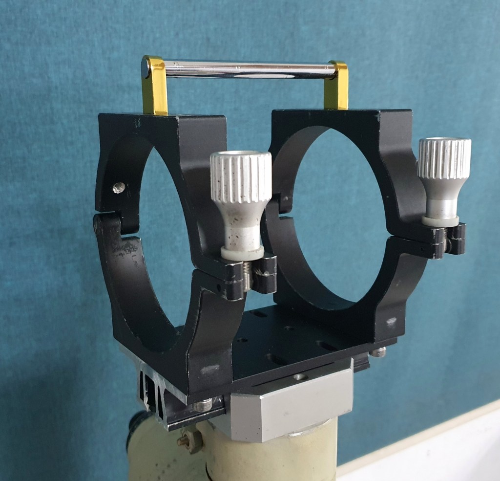
I have used door handles to serve as my telescope’s carrying handle. A carrying handle allows for easy transport of a telescope, especially for mobile setups that need to be assembled and disassembled with each imaging session.
The carrying handle was attached directly to the mounting rings, secured with two screws flushed underneath.
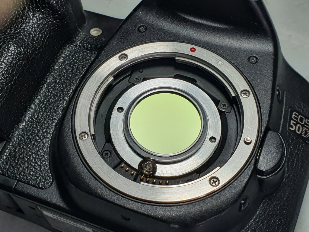
I have built a DIY clip-in filter holder for use with my DSLR. I used a spare T2 to 1.25 inch adapter supplied with my astronomy camera. I noticed that my Canon 50D has space to accommodate this adapter. I then drilled a small hole in the camera and used a small screw to fasten the DIY clip-in filter in place.
DIY clip-in filter for DSLR
The clip-in filter works best with modified DSLR cameras with the stock filter removed. It can be used to mount 1.25 inch filters such as a dual band filter and a UV-IR filter. I have also made a clip-in stock filter so I could still use the modified DSLR for daytime photography.
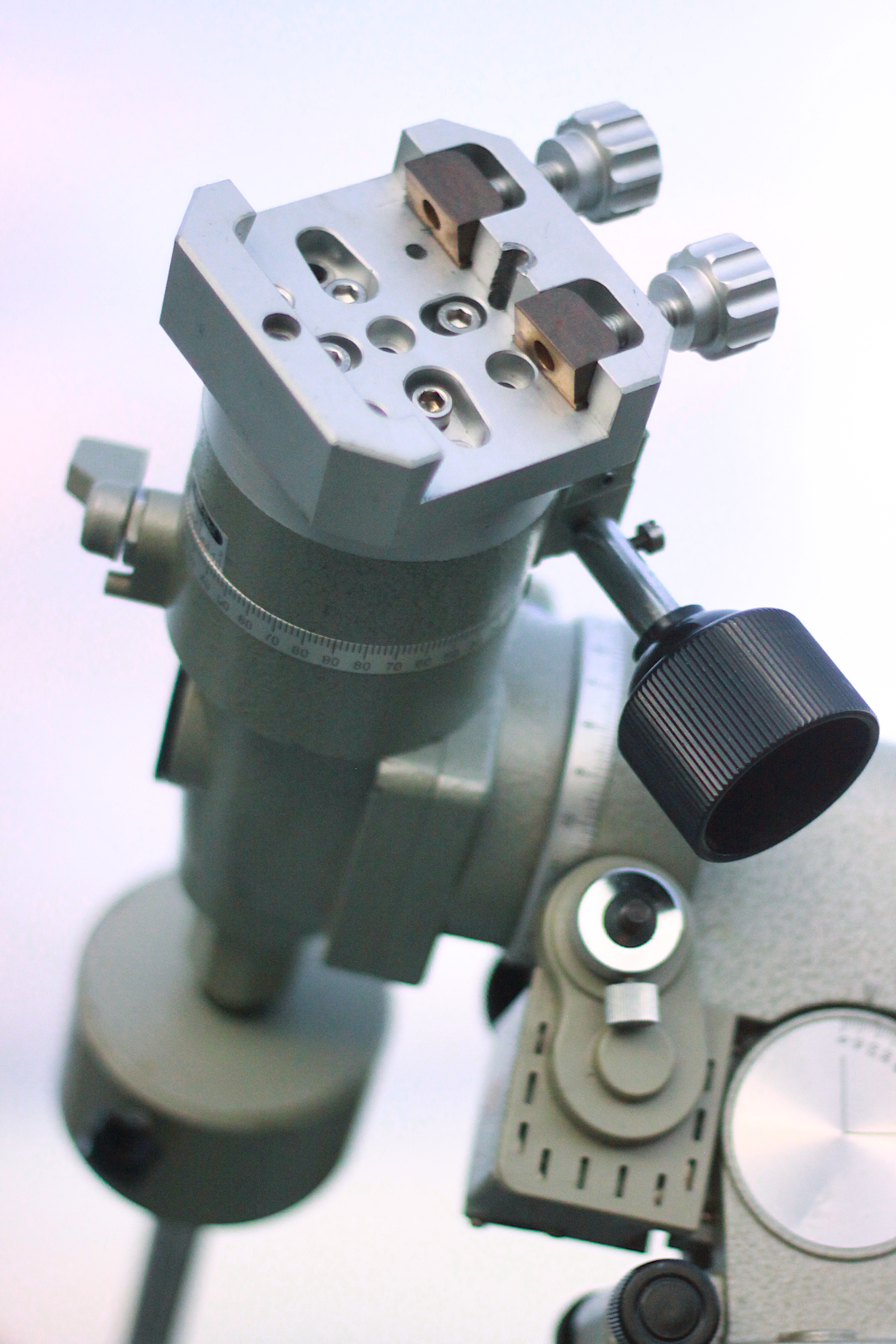
I have installed a dovetail clamp to my Vixen Super Polaris mount. This modification allows easier swapping between mounts and telescopes, since my two other telescope mounts (Meade LXD75 and Vixen Great Polaris) both have Vixen-style dovetail clamps.
Dovetail clamp
I removed the bar that the telescope’s saddle originally attaches to then drilled and tapped holes to fasten the dovetail clamp to the mount with screws. This clamp will be carrying a very light payload.
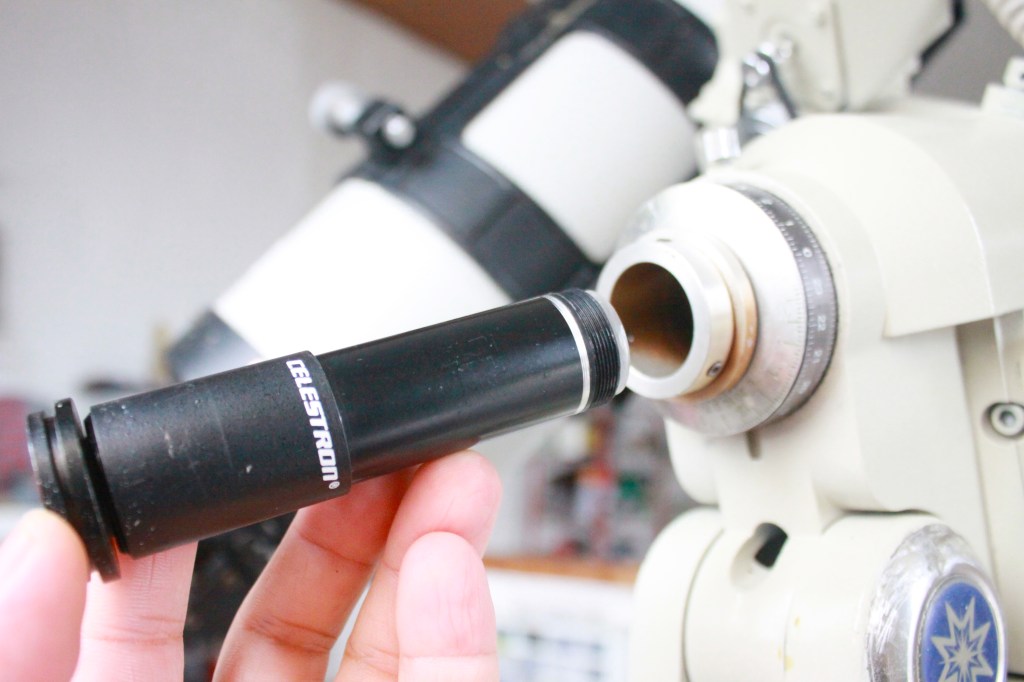
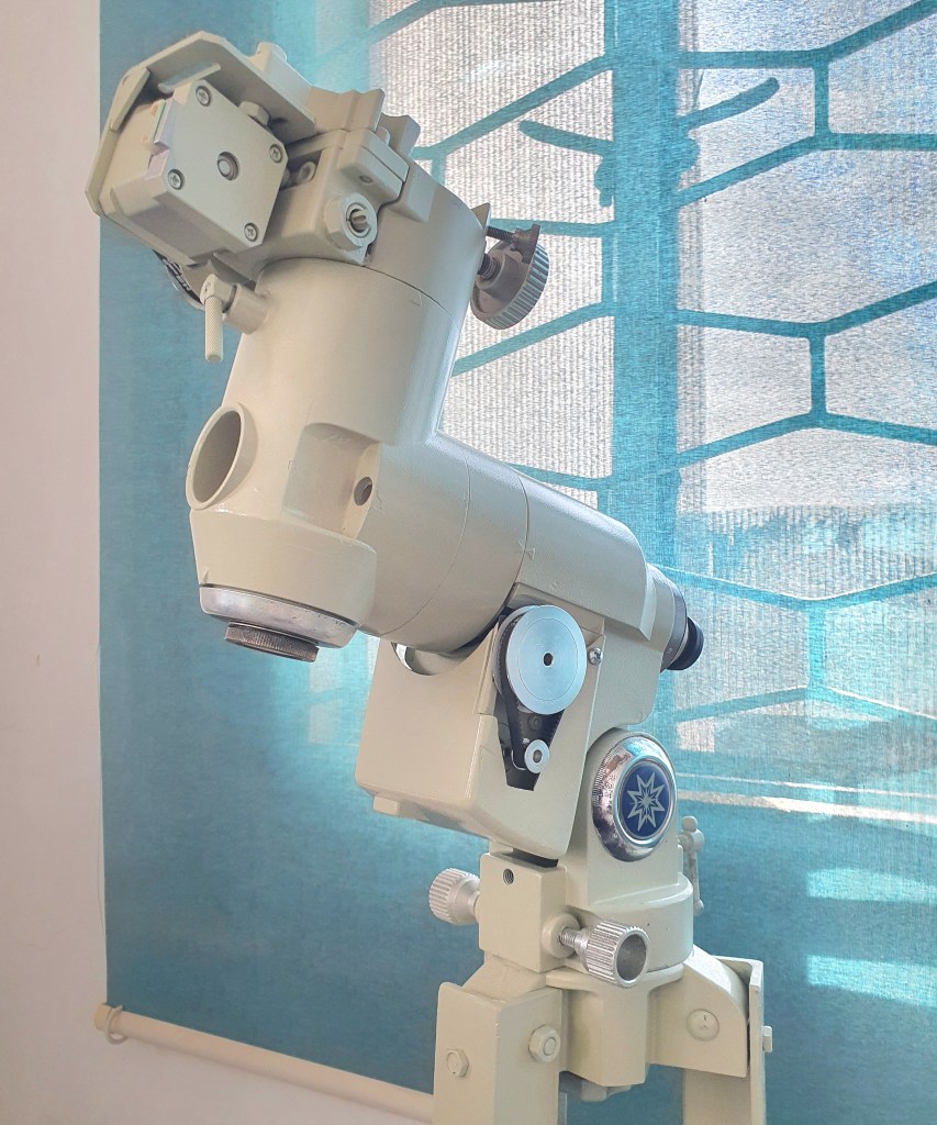
I have recently acquired a Meade LXD75 mount without a polar scope. I noticed that a small finder scope could fit in the polar scope slot, thus, serve as an improvised polar scope. I looked for a small finder scope and it so happened that an 8 x 20 Celestron finder fits the slot. I have made some modification in the finder scope’s barrel to make sure it clears the polar scope slot. Notice that the finder scope’s barrel has been modified, with a smaller barrel diameter towards the objective lens, otherwise it would not fit all the way through and protrude too much.
A repurposed 8 x 20 Celestron finder scope used as a polar scope
I tested the improvised polar scope on a clear night to see if I would be able to spot Polaris and roughly polar-align the telescope. While it lacks a star map overlay, a usual feature in a standard polar scope, it has a cross hair for tracking the position of Polaris relative to the position of the mount’s RA axis.
For astrophotography, a more accurate polar alignment method is needed such as the drift alignment method. In drift alignment method, when the telescope is pointed and tracking a star in the east, minimize the north-south drift in the eyepiece by moving the polar axis higher or lower (altitude adjustment). When the telescope is pointed and tracking a star in the celestial equator (near meridian), minimize the north-south drift by moving the polar axis to the left or to the right (azimuth adjustment).
The original controller of this Meade LXD75 mount has failed and a DIY OnStep controller was used to repair the mount and restore its tracking and go-to capability. I have installed RA and declination motors and used an Arduino microcontroller to control the motors. Just like the mounts typical of this class and era, it has a 144:1 main shaft gear reduction, and looks very similar to the Vixen Great Polaris mount. It takes 144 full rotations of the worm to rotate the RA or declination shaft 360 degrees.
I used NEMA 17 stepper motors on an L-brackets with 16-teeth and 60-teeth pulley and belt drive system for each axis. The total steps are 200 steps * 60/16 reduction * 144/1 teeth worm drive with 1/64 micro-stepping, at 6, 912, 000 per 360 degrees, or 19,200 per degree.
The mount uses an Arduino Mega 2560 as the main controller board, a pair of LV8729 stepper motor driver, and an HC-05 Bluetooth module (which connects to the OnStep Android app). It is powered by a 12V 12A power supply. To watch a video of this Meade LDX75 OnStep conversion during testing, click here.
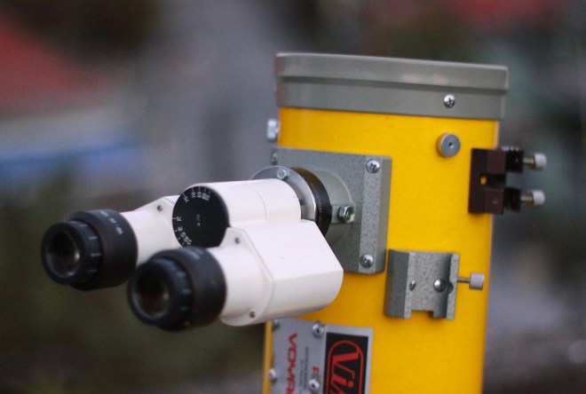
I attached a binocular eyepiece (or binoviewer) repurposed from an old microscope to a reflecting telescope. A beam splitter prism splits the light and send it to two eyepieces. The image viewed on each eyepiece will be less bright (half brightness), but since both eyes see the image, the view appears to have an enhanced perception of depth.
I’ve built a simple binocular parallelogram mount for my 10×50 binoculars, to provide precise and smooth motion during extended visual observations. A repurposed desktop lamp mount was sturdy enough to support the weight of a small binoculars. It can be moved around freely yet remain in place when pointed at a specific part of the sky.
The parallelogram mount attaches to a Vixen altitude-azimuth mount. It allows coarse and fine adjustments through the motion control knobs. The DIY mount connects directly to a standard binocular mount. It uses springs to provide balance instead of a counterweight, with short parallelogram bars and tighter fastening screws for better stability.
I’ve tested the parallelogram mount for lunar observations and for scanning the Milky Way. With this DIY mount, the binoculars can be pointed at any target from horizon to zenith with comfort and ease, eliminating the strain on the hand and unsteadiness associated with unmounted binoculars.
Due to Earth’s rotation, objects in the sky appear to move from east to west. Taking a long-exposure photo of stars using a camera on a non-tracking mount will produce trails. To compensate for the Earth’s rotation, a tracker as simple as a geared stepper motor can be used. This tracker is controller by a simple Arduino-based stepper controller.
Ultra-portable tracker for DSLR cameras
Any geared stepper motor with sufficient torque can be used as a drive mechanism. For this project, I used a stepper motor with a built-in 1:500 gearbox.
I simply attached an aluminum plate to the end shaft of the stepper. A ball head mount was then used to connect a DSLR to the plate. All the components can fit easily in a small camera bag. It is designed to carry only a very light payload such as a DSLR with a wide-field lens.
Milky Way imaged with an 18 mm lens at 90 seconds exposure, with and without tracking.
Calibrating the DIY Tracker
The tracker’s ‘tracking speed’ needs to match the actual movement of the sky. Calibrate your own tracker by making sure that the stepper does not rotate a bit too fast nor too slow. Align the tracker’s axis of rotation (or what is called the polar axis, which in this case, the stepper’s main shaft) with the north star Polaris (for observers in the southern hemisphere, point the tracker’s polar axis in the general direction of the Earth’s southern polar axis). Point the camera to any bright star. Turn the tracker on and start tracking the sky. Take a series of shots (with just enough exposure to reveal the position of stars). By looking at the live view images or photos taken, you should be able to tell whether or not the tracker is moving too fast or too slow.
Polar Alignment
Before attempting this method, make sure that you have already calibrated the tracker, that is, you’ve managed to achieve a correct tracking rate. When pointed to a star in the east, minimize the north-south drift by adjusting the polar axis higher or lower (altitude adjustment). When pointed to a star in the celestial equator (near meridian), minimize the north-south drift by adjusting the polar axis to the left or to the right (azimuth adjustment). The east-west drift is corrected by adjusting the tracker’s speed.
Telescope clock drive controller based on L293D and Arduino Uno board
//Simple clock drive controller by Anthony Urbano 06 September 2021. It uses an Arduino Uno and an L293D.

#include <AFMotor.h>                  //Go to SKETCH > INCLUDE LIBRARY > then lookup "Adafruit Motor Shield Library"
AF_Stepper motor1RA(24, 1);           //Initializing motor's steps per one full rotation; Connect the motor to M1 port
void setup()
{
}

void loop()
{
  motor1RA.setSpeed(100);              //Change the value to speed up or slow down the tracker
  motor1RA.step(1, FORWARD, DOUBLE);   //Motor takes 1 step forward; to reverse direction, replace FORWARD with BACKWARD
}
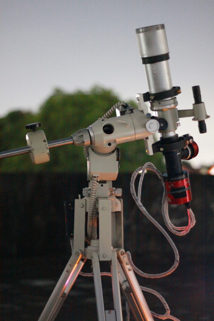
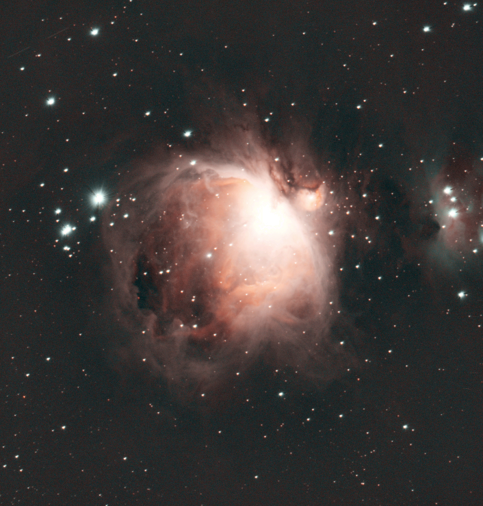
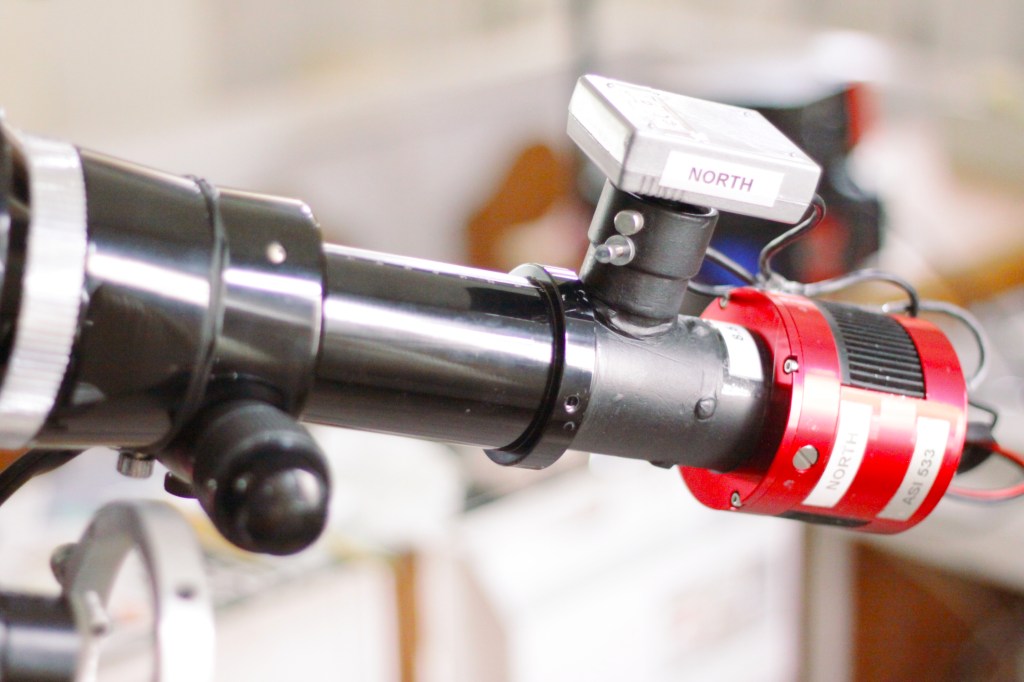
The Celestron Travel Scope 70 has a front lens diameter of 70 mm and a focal length of 400 mm. A telescope with these specifications works well for terrestrials observations, and if mounted on a tracking mount, may produce good results in long exposure imaging. Due to its small aperture and short focal length, it has a very limited use for astronomical observation (only good for low power views). Note that the telescope showed signs of chromatic aberration.
Celestron Travel Scope 70 with modified focuser, ASI 533 astronomy camera, and mounted on a Meade LXD75 tracking mount
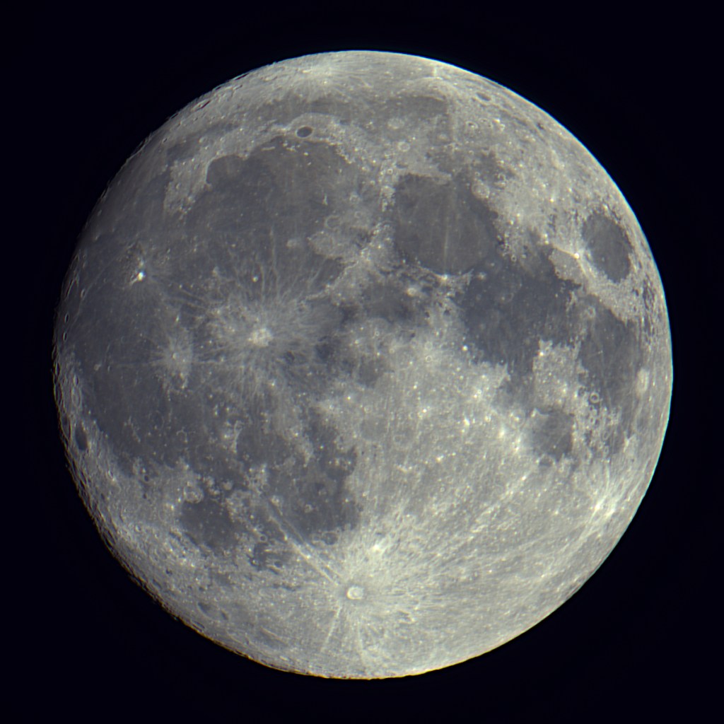
Moon imaged with a Celestron Travel Scope 70, an ASI 533 astronomy camera, and a Vixen GP tracking mount
Orion Nebula M42 imaged with a Celestron Travel Scope 70, an ASI 533 astronomy camera, and a Meade LXD75 tracking mount
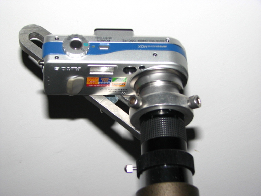
A universal camera adapter allows any camera to be attached to a telescope or binoculars. This imaging method is called afocal imaging, in which a camera with its lens is mounted next to another image-forming optical system such as a telescope or a pair of binoculars. This adapter was built in 2008 and still in use today.
A universal camera adapter for connecting any camera with any telescope
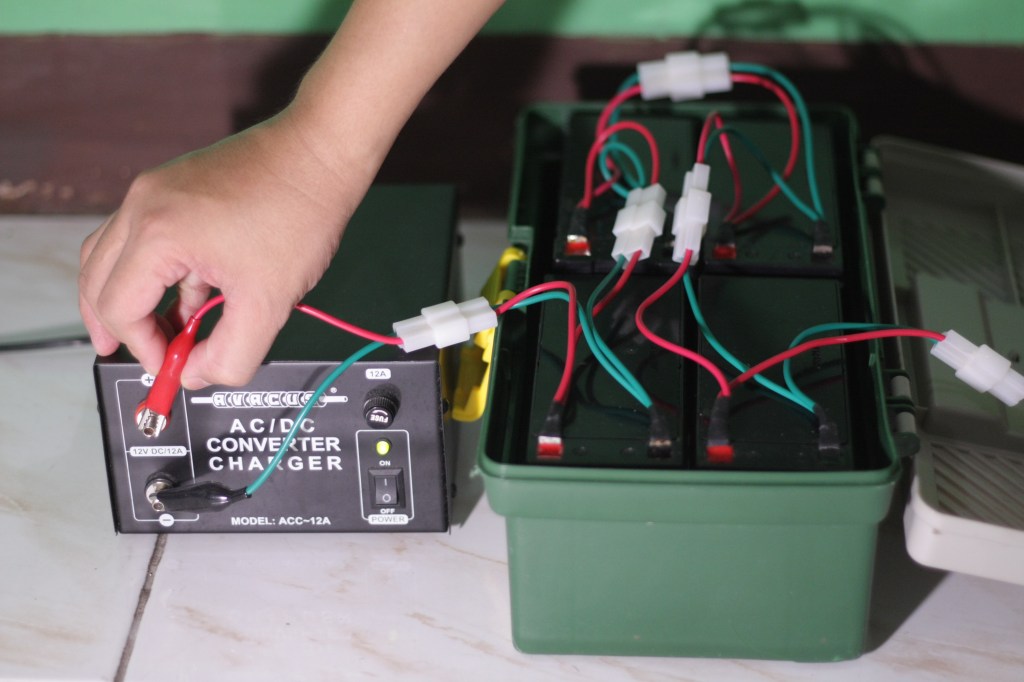
Over the years, I have used various types of batteries, but the one I use most often is the deep-discharge lead-acid type. They are robust, low-cost, can be charged with almost any compatible power supply, and most importantly, can double as a vehicle jump-start kit when not being used in the field. I use four 12V 9Ah deep-discharge lead acid batteries connected in parallel, to power the laptop, and another 12V 9Ah battery for the telescope’s tracker. These batteries remain usable for 2 to 3 years.
A modular field-battery to power my equipment during remote imaging sessions
A moderately-sized field battery has more than enough power to last an overnight imaging session.
I have built an OnStep go-to telescope controller for a Vixen Great Polaris mount. I used an Arduino Mega 2560 as the main controller board, a pair of LV8729 stepper motor driver, and an HC-05 bluetooth module (which connects to the OnStep Android app).
I also built a Smart Hand Controller (SHC) using an ESP32 module, an OLED display, and a button array. The SHC connects to the same serial communication lines (Rx and TX pins) used by the HC-05 bluetooth module. I use a toggle switch to select between the HC-05 Bluetooth module for the Android controller and the Smart Hand Controller with ESP32 module.
I used a pair of 200-step-per-revolution stepper motors paired with 60-teeth and 16-teeth pulley and belt drive system to motorize the Vixen Great Polaris mount with 144:1 worm drive. In this configuration, the total steps are 200 steps * 60/16 reduction * 144/1 teeth worm drive = 108,000 steps per 360 degrees at full stepping. Actual testing showed that accurate tracking is possible even at just 1/64 microsteps (as evident in a 60 second unguided exposures at 900 mm focal length). This brings the total steps per revolution to 6, 912, 000 per 360 degrees, or 19,200 per degree. You need to configure these values in the OnStep code.
The OnStep telescope controller can be connected to NINA to enable automatic slewing to targets and use plate-solving to validate and refine its pointing accuracy. It also connects with Stellarium to display real-time the telescope’s current position.
OnStep will have very accurate pointing and tracking even with just one-star alignment, if properly polar-aligned.
I have installed a laser pointer to my telescope as a tool for locating objects. The laser pointer is mounted on a finder scope holder with collimation screws to enable alignment with the telescope. It has a toggle switch that allows the laser to be turned on and off.
Using laser pointer as a finder
To find an object such as a galaxy or a nebula, I turn the laser on and point the telescope to the target’s approximate location as indicated in a star map. If the target is too dim and there are no bright stars in the vicinity, I just use a pair of binoculars to spot the target and then slew the telescope manually to the target. The laser allows me to know precisely where the telescope is pointed at, and then use the laser to guide the telescope to the target. Observe safety precautions when using laser pointers.
To view posts on DIY projects and astronomical equipment, click here.
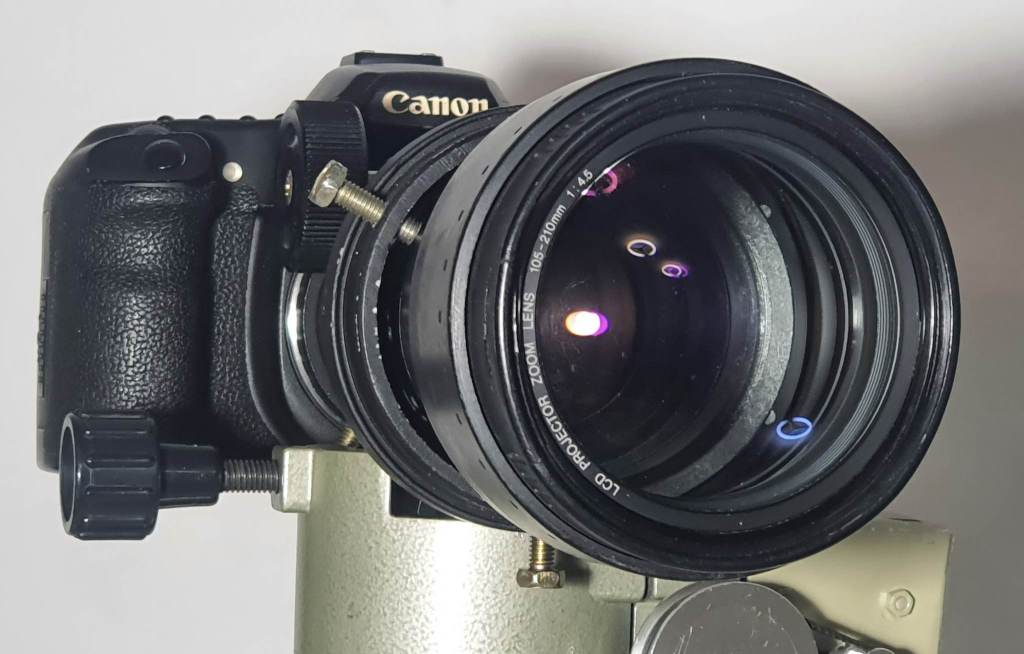
Projectors have lenses that may be used to build low-magnification telescopes. I happen to have found an old 70 mm diameter LCD projector lens with focal length of 105-210 mm which I paired up with an eyepiece to build a DIY telescope.
DIY projector lens telescope
This projector lens, while not designed to be used as a telescope lens, may still provide good views. I measured the proper focus distance and used a DIY adapter to attach a 2-in diagonal mirror and a 40 mm lens to it. This combination produced a 2.6 by 70 to 5.25 by 70 finder scope (wide field of view with ability to zoom). Focusing is done by sliding the eyepiece in and out of the diagonal’s eyepiece holder. I then made an improvised reticle (cross hair) to finally complete the setup. I will be using this DIY projector lens telescope in star-hopping to deep-sky targets and scanning large areas of the sky.
Focal reducers are optical elements (a convex lens or lens group) that converge light from a telescope’s objective. It shortens the focal length and in effect, produces a faster telescope (lower f/ratio) and widens the field of view (larger portion of the sky is imaged). Any decent quality objective lens from an achromat telescope or a finder scope could work as a focal reducer. DIY focal reducers may introduce aberration (coma) and must be considered when attempting this modification.
Using a Vixen 90 mm Objective Achromatic Lens
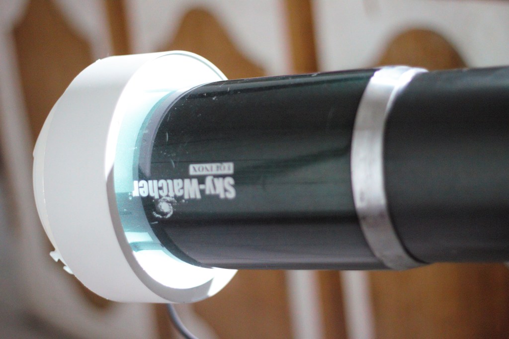
I have built a DIY focal length reducer (focal reducer) by inserting an objective lens from a 90 mm Vixen achromat along the optical system of a Sky-Watcher Equinox 100ED . The telescope’s native focal length is 900 mm at f/9. Using the objective lens of a Vixen 90 mm f/14 achromat, the focal length of the Sky-Watcher Equinox 100ED is reduced to 557 mm at f/5.57. To reach focus, I had to shorten the optical tube to about 55 mm. The focuser’s draw tube was also shortened to prevent it from obstructing the light and stopping down the objective lens when the draw tube moves inward. Varying the distance between the main lens and the reducer lens affects the resulting effective focal length. From 2020 to 2024, I have tried placing the DIY reducer at various distances until I finally found one configuration that produces stars with acceptable sharpness. To view a sample photo with a DIY reducer using a Vixen 90 mm achromat objective lens, click here.
DIY focal reducer using an objective lens from an achromat refractor with an improvised lens cell
Using a Threekor 40 mm or 50 mm Finder Scope Lens
Finder scope lenses can also be used a reducers. I have used the objective lens of a 40 mm Threekor finder scope as DIY reducer for my 8 inch Celestron SCT. I just removed the finder scope’s lens and then placed it at the threaded end of the 8 inch SCT, where you would attach a visual back adapter. I used a spare tube extender (I use M42 spacers) to mount the lens and insert it into the optical path. Upon testing, it reduced the focal length from 2000 mm to 1140 mm. I have also successfully used a 50 mm finder scope achromat lens as a DIY reducer. To view a sample photo with a DIY reducer using a 40 mm finder scope achromat objective lens, click here.
DIY focal reducer using a finder scope lens attached to a tube extender using super glue
I have built a DIY off-axis guider (OAG) using a mirror from a DSLR camera, some tube extenders (2 in and 1.25 in diameter), and a webcam. To build the OAG, I removed the lens from a Barlow so I could get a 1.25 inch barrel for the webcam attachment, and then fastened it perpendicular to a 2 inch extender, where an appropriate side hole has been made. I then fabricated a small mirror mount (like a secondary mirror mount in a Newtonian) using some brass material, to send the reflected light on to the side. The placement of the mirror and the proper spacing to achieve focus required trial-and-error.
DIY Off-Axis Guider (OAG)
In off-axis guiding, the telescope functions both as an imaging scope and a guide scope. In this configuration, a mirror or a prism receives a portion of the light without blocking the main imaging sensor, sending the light to a guide camera. In this build, I used a high-quality mirror I happen to have found in a non-working Canon 1100D. To use the improvised OAG, focus the main camera first, and then slide the guide camera in or out to achieve focus.
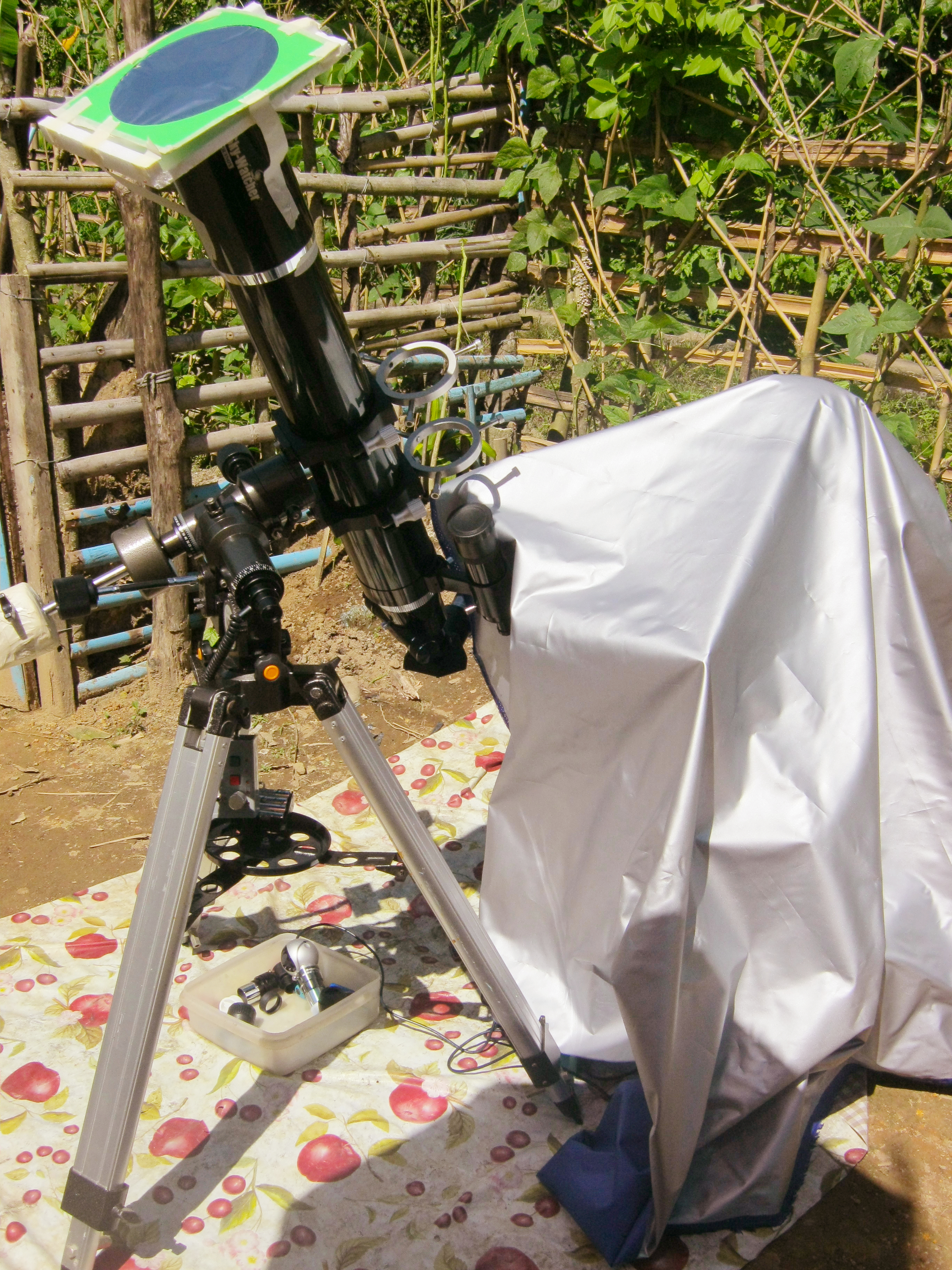
I have been using a Baader Neutral Density (ND) 5.0 Solar Safety Film filter for several years now in solar photography and visual observation. According to the specifications, it reduces solar intensity by a factor of 100,000. The Baader ND 5.0 solar filter produces sharp images with good contrast without changing the white balance.
Baader film solar filter mounted on a telescope
The filter looks like a thin reflective plastic sheet, about A4 size (20 cm by 29 cm). When used with binoculars or telescope, it must be cut to the right size to cover the whole aperture of the optical instrument and installed securely on a rigid frame. Alternatively, the filter may be used without a telescope. Based on my experience, while the solar film may look very delicate and fragile, it is very durable and does not easily get damaged. Special attention, however, must be given to ensure that the film does not get stretched or folded to retain its properties. The filter I purchased in 2011 which has been used extensively in almost every solar event visible in my locality is still in excellent condition.
To view posts on DIY projects and astronomical equipment, click here.
I’ve built a DIY dedicated flat field panel using a repurposed LED light fixture. The flat field panel is a light source with relatively uniform brightness. The panel attaches directly onto my telescope and can be used for taking flat frames.
DIY LED fixture for taking flat frames
With a DIY flat field panel, the unevenness in the illumination of the field such as vignetting and presence of dusts are revealed. When a flat frame is applied to an image, any variation in brightness or illumination across the frame is leveled out (flattened), thus, vignetting and dusts are removed from the image.
Here’s a sample photo with and without flats calibration frames applied.
To view posts on DIY projects and astronomical equipment, click here.